Monday, May 13, 2013

Cylinders And Other Geometry

The end of my last post saw us with a chassis ready to solder together. Well, almost.

We need to address two things with the chassis first. The rear of both side-frames has an ear which is bent to 90deg away from the chassis. These support the rear of the cab/boiler assembly. You will find this arrangement on many locomotive kits. I generally fit what is going to be attached to these ears later before I solder the rear spreader in, just to keep the two aligned correctly so that assembly later is not an issue. This may sometimes see them having to be re-bent or simply adjusted a little so that all is well. Doing this now will save a lot of heartache later.  For bending things like these ears, I use a HOLD N FOLD from Gwydir Valley Models. You do not need one as a good smooth jawed pair of plyers will suffice, but it does make bending brass a lot easier and neater. Once you have one, you will not part with it.


By the way, the photos in this blog entry are of an NN chassis which is very similar to the 35, funny that. I constructed this one while at Kaleen Model Rail Show this year demonstrating to modellers and the general public. I have not even cleaned it yet..... You can tell by the little bit of blue grease beside the RH ear. This is the copper being leached from the etching by some LACO flux residue. That is the only downfall of the flux. A quick bath is warm soapy water will fix that.

The second and most important, is to ensure that the wheels and axles are going to be square to the rail-head.

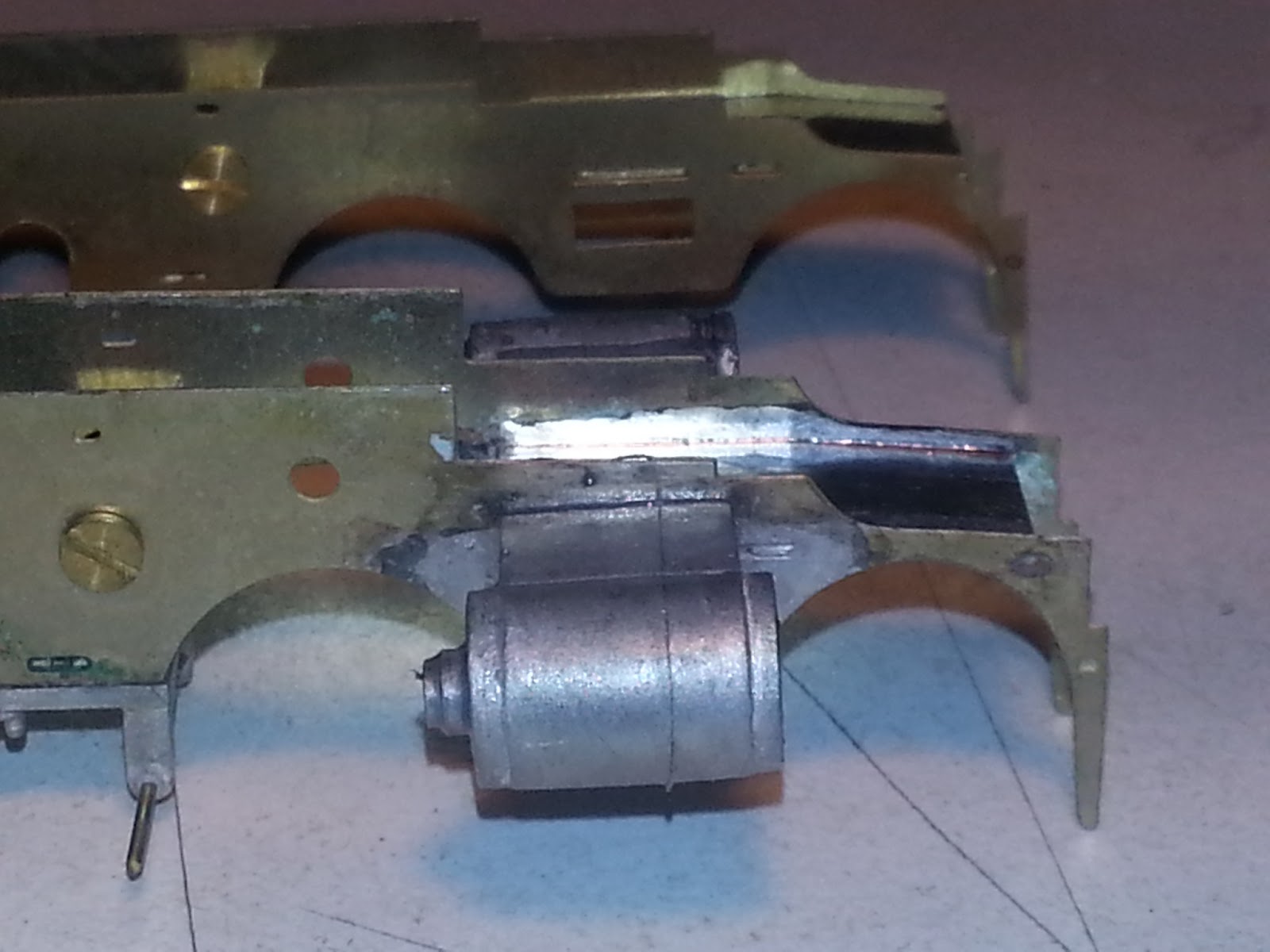
Locate the bearing cover plate, the white metal casting fitted below the chassis in the picture above, clean it up and give it a buff with a soft brass brush to remove any oxidation and or mold release. Locate and clean up the spring castings and fit them AFTER you fit the cover plate to the chassis with the screws supplied for the purpose. This will ensure that it all stays straight and square. For this job I use BGM flux and BGM or Carr's 70 solder. Your Iron needs to be set about 200C.


You can now clean up, fit the bearings axles and wheels and check all is good. Once happy that the chassis is square and they generally are pretty good as long as care is taken in assembly, carefully remove the wheels and axles, set them aside and solder the chassis together.

For this I use LACO soldering paste and Carr's 145. Carr's 188 can be used if you have a lot of finer detail to add. You then use the 145 for the extra parts. In this case there is not a lot to add and we can manage with just 145. Your iron should be set to approx 400C for this

Cylinder castings are generally, as in this case, cast in white metal. We need to solder these on. Yes we could glue them using an epoxy, but solder is a much better option. Clean up the castings, removing any flask or dags from the casting. I usually smooth any parting lines around the cylinders after I have fitted them as they are easier to handle then. To check that the cylinders are lined up properly, remember that a line directly through the cylinder will line up with the centre of the driven axle.

We cannot solder white-metal directly to brass or nickel in one easy step. There are some who will tell you differently. I have never been successful doing so. After you have dry fitted the cylinders a couple of times and are happy, pre tin the area they will mate against on the chassis with Carr's 145. Turn the iron back down to 200C and using the BGM flux and Carr's 70, fit the cylinders. Unlike when using glue, if you do not get the cylinders fitted correctly first go, you can reheat and adjust or simply remove with some boiling water. You can fit the wire supports for the brake gear to the white metal cover plate using the same method.

We can have use Carr's Red flux for white metal soldering. BGM flux has much better wicking characteristics which are extremely valuable to us.   

   
Identify the cylinder covers and fit them. Care needs to be taken here that you do not heat the cylinder enough to remove it from the chassis. Don't be tempted to lower the temperature of the iron much below 200C. Some people do this in an attempt to keep the job cooler. You are better keeping the temperature up so that you complete the job quicker and are able to allow cooling a lot earlier.

So now we have a chassis that is starting to look one. Here are the two chassis side by side to see how much we have done.

In readiness for next time, locate the boiler, smokebox and footplate. You can clean these and dry fit them. Remove the molding tubes across the footplate openings with a say not side cutters. Side cutters can distort the footplate. Also locate the crossheads and crosshead slide etches. We will fit these as well.

Til next time, keep the irons hot..

Macca


Saturday, March 16, 2013

Starting The Project

Let's get this loco started.

A good chassis is the base for a good model. Extra time and care spent now will repay you with years of trouble free operation, especially with a steam locomotive.

Here are the two bags of bits that we need to take pieces from to begin our chassis. By referring to the instructions identify all the required parts. For our 35 class, we need both chassis halves, 4 etches which will be soldered in between the two chassis halves and 2 solid spacers machined from square bar. Part numbers, 136, 142, 139, 140x2, 141 and 138x2. 4xM2 screws are also required.identify and collect the needed parts.

Carefully remove parts from the etch to avoid bending or damaging them. Many methods have been offered at different times. Some use a knife and a block of wood, say use a small chisel against the block of wood. I have used both these methods but actually prefer a small pair of metal shears. Sometimes I even use a Dremel with a small work wheel.

Tip number 1.... Get yourself a container to store parts which are not immediately used. 

I like to compare the two chassis halves to each other, to ensure that they are in fact the same. Put them back to back and see that all the holes and such line up together.

Some chassis use a bearing soldered in for the axles. This one uses a bearing which will be trapped by a cover plate. A much better arrangement I think, especially for future servicing or replacement of parts.Use care and work slowly with a file until they just fit.  


There will be some cleaning up to do. You can use jeweler's files to do this. Make sure there is no distortion around the check outs for the axle bearings from the manufacturing process. A gentle tap with a small hammer will fix that. Do not use heavy blows as this will do more damage than good. Carefully and slowly file just enough material so that the bearings fit just snugly


Take the solid spreaders and clean any burrs around the screw holes in the ends with a drill bigger than the hole. I generally use about a 1/8" drill mounted in a file handle. This will firstly allow the chassis to sit flush against the spreader and allow the screw to travel into the spreader properly. The base of the screw may not initially travel fully into the spreader. Using your 1/8" drill again, take a little more material from the screw hole until it does. Just a few turns will do.

By referring to the instructions, identify right and left sides, using the spreaders, (138), join the two halves to begin construction. If the screw holes in the etch are tight, open them with a small rat tail file or a cutting broach. The forward etch spreader, has a shallow bend. you can generally do this with no tools, but a pair of smooth jawed plyers may help. I use a Hold and Fold bender, available from Gwydir Valley Models, but it is not really necessary. It does however make the job easier and often much neater. Bend a little at a time until it sits in the rebates in the chassis. Back off one screw and fit it. Do the screw up again. fit the other three now the same way. The rear etch spreader has a small terminal attached. You can add a short length of wire before painting, or simply tin the tag and scrape the paint off later, when you fit the motor and gear box.


Page 6 of the instructions shows the motor and gearbox being fitted at this point, along with the wheels and axles. I do not do this. In fact the motor and gearbox are always fitted last by me, or at least after the chassis is rolling sweetly and is painted. The steel axles will not take kindly to being washed and a far better paint job can be achieved without them fitted.

What we will do though, is test fit the wheels and axles and see that everything is square. Once happy, we can solder this much together.

I use a Dick Smith T-2200 set to approximately 400C for this job, with LACO Regular Soldering Flux Cream, available at Reece Plumbing and Carr's 145 or 188 solder. 179 could also be used. You could use Carr's Green label Flux, Baker's or a number of others. I like Laco as it is a cream and easy to apply. It is also not toxic and non corrosive. Don't forget to clean up. I use Simple Green All Purpose Cleaner which I obtain at Bunnings.


If you have any questions, join Soldering Techniques Facebook page. Hopefully we can sort your query for you.

 http://www.facebook.com/groups/497428973606817/
 
Til next time, keep the irons hot.....                                            Macca.


Thursday, February 14, 2013

Building a Brass and Whitemetal Loco

Preamble...

As noted previously, I have been encouraged to share my soldering knowledge via this blog. I will be assembling a DJH Kit of a New South Wales Government Railway's 35class.

The kit comprises everything we need apart from solder, flux, paint, decals and brass numbers.

So what do we need to build a loco? Firstly and most importantly, we need the patience to ensure that at each step we are assembling the kit correctly, with the right solder and flux and of course that the model is as accurate as we are capable of making it. There are hundreds of photos available of the 35 class and it is worth perusing as many as you can collect. An accurate, cleanly assembled, well running model is a joy to behold and I still feel pride every time I finish one.

The products and techniques that I use have been tried and trued during the assembly of well over a hundred locos for myself and friends. They are not the only products and techniques, they are simply what I have found to work each and every time.

Tools

You will need a temperature controlled soldering iron. I use a Dick Smith T-2200. These are no longer available at the stores but you may be able to acquire one on line. I noticed that a tools link on the ARKits website has them available. I have no idea about numbers. I use the largest tip available for the iron for good heat transfer. Jaycar have a suitable Solder Station. TS1390. Buy the TS1394 tip with it.

An assortment of files will be needed. I have a lot of jeweler's files as well as a couple of single cut Mill Bastard files.

Various knives, scalpel and or Exacto types are ideal. We will cover the specific types I use as we go along.

Drill bits are essential. Packs of assorted drill bits in 0.1mm steps are readily available. A 1/8 inch is also required. Buy spares of 0.5mm as you will break a few. A couple of pin chucks are handy, at least for the smaller drills. Try and track down a little bee's wax to lubricate your drill bits.

Something for cleaning the whitemetal is essential. I use a suede shoe brush, hard to find now, however, AMRA NSW were able to source some after I conducted a work shop in their rooms. A glass fibre pencil is also very handy, but extreme care should be exercised with it. 

My Dremel is something I just cannot cope with out. I built a few locos before I bought one but found the investment well worth it. DON'T PUT SMALL DRILL BITS IN THE DREMEL. You will fry them. 

Solder and Flux.

I once stated at a work shop that I had quite a range of fluxes and solders that I used. I have now reduced the range to only a few. I use BGM flux and their solder or Carr's 70 for whitemetal. I use LACO Regular Soldering Flux for brass to brass and for tinning brass before joining to whitemetal parts. Carr's 145 does the majority of my brass soldering. Sometimes I will use a little Carr's 188 or 179, but rarely.

How and where will be discussed as we travel along.

My next post will show, yes with pictures, how I assemble the locomotive chassis. come back regularly and check on my progress. If you have a specific question regarding this build or indeed another, I can be contacted through the Facebook Group Soldering Techniques, Murrumbidgee Mail, or through this blog.

Macca